ASB Remote Interface vs. Launch SmartLink C – care este diferența?
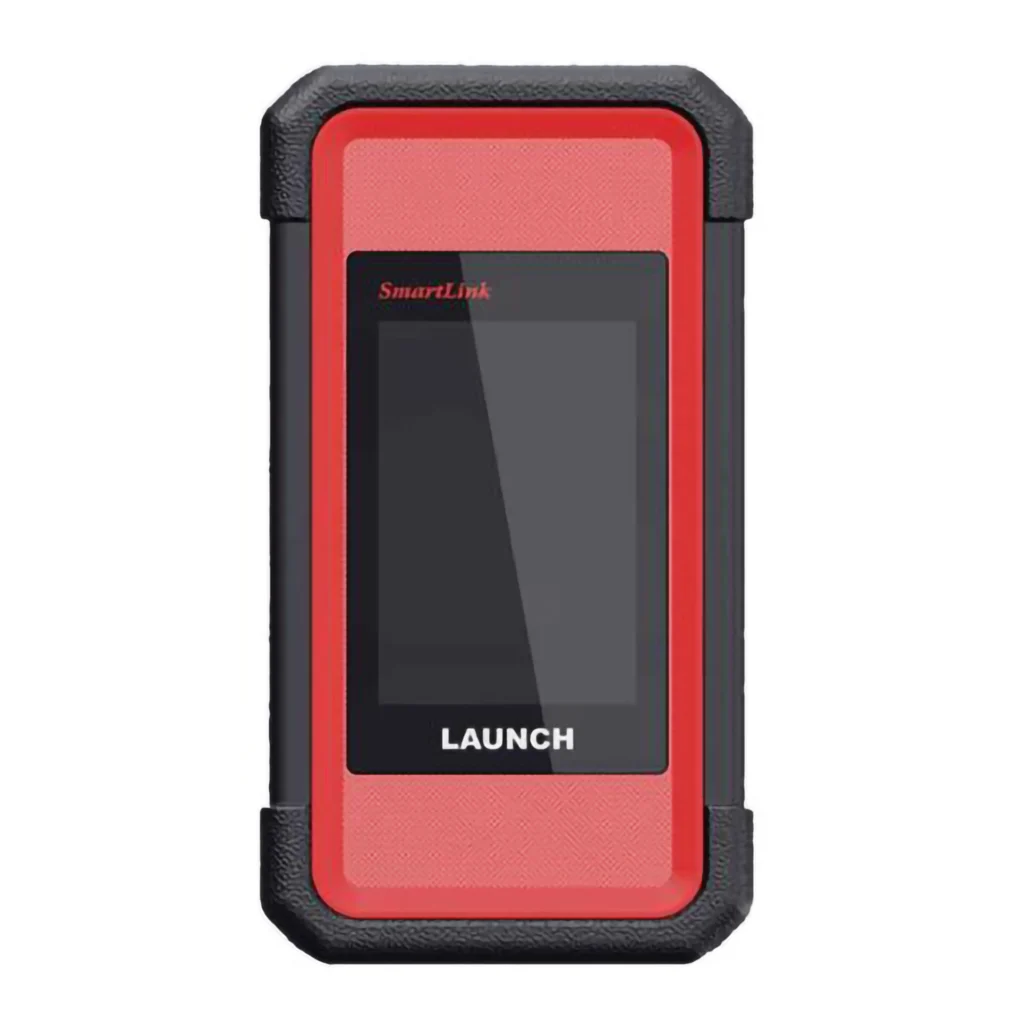
1. Prezentare generală ASB Remote Interface Interfață dezvoltată și proiectată special pentru diagnosticare și codare la distanță, dedicată service‑urilor care folosesc frecvent serviciile remote și vor costuri clare, fără taxe pe fiecare conexiune. Launch SmartLink C Modul original Launch, livrat sau achiziționat împreună cu anumite testere Launch X‑431, care permite și diagnosticare/codare remote prin platforma SmartLink, pe baza unor plăți per conexiune sau abonament. 2. Tabel de comparație Caracteristică ASB Remote Interface Launch SmartLink C Scop principal Diagnosticare & codare remote (remote only, dedicat) Modul VCI + remote pentru testere Launch X‑431 Cine l-a proiectat Proiect dedicat pentru asistență remote de catre Jifeline Netherland Proiect Launch pentru diagnoză + funcții remote Cost suplimentar conexiune pentru clientul final 0 € / conexiune – fără cost suplimentar pe sesiune ~10 € / conexiune sau abonament, în funcție de platformă Costuri recurente Fără taxe pe conexiune pentru clientul final Abonament anual și/sau taxă pe fiecare conexiune remote Frecvență de utilizare recomandată Ideal pentru utilizare frecventă / zilnică Recomandat pentru utilizare ocazională / rară Echipament necesar Interfața ASB Remote Tester Launch X‑431 + modul SmartLink C Tip utilizator Service-uri care fac des programări/codări remote Garaje care folosesc rar asistența remote Optimizat pentru Remote coding, remote programming, suport tehnic intens Diagnoză Launch + acces punctual la servicii remote Costuri pe termen lung Foarte avantajos la utilizare intensivă Avantajos doar dacă folosești rar serviciile remote 3. Când alegi ASB Remote Interface? Alege ASB Remote Interface dacă: ai nevoie des de programări și codări la distanță; lucrezi frecvent cu: adaptări, inițializări, codări complexe, suport tehnic remote recurent; vrei să eviți: plata fiecărei conexiuni, surprize la costuri pentru clientul final. Beneficiu principal: Nu există niciun cost suplimentar pe conexiune pentru clientul final – ideal pentru service‑uri care folosesc intens serviciile remote. 4. Când folosești Launch SmartLink C? Launch SmartLink C este o alegere bună dacă: ai deja un tester Launch profesional cu modul SmartLink C inclus sau achiziționat; folosești ocazional asistența remote (de ex. câteva cazuri pe lună); ești confortabil să plătești: fie un abonament anual, fie ~10 € pentru fiecare conexiune remote. Beneficiu principal: Dacă ai deja SmartLink C, poți începe imediat să folosești serviciile remote, fără achiziții suplimentare de hardware. 5. Recomandarea noastră Utilizare rară remote → SmartLink C este suficient, mai ales dacă îl ai deja în pachet cu testerul Launch. Utilizare frecventă remote → recomandăm ASB Remote Interface, ca să: elimini costurile pe conexiune, ai un sistem dedicat pentru diagnosticare și codare la distanță, controlezi mai bine costurile pe termen lung
ASB Remote Interface vs. Launch SmartLink C – care este diferența? Read More »